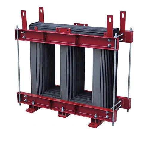
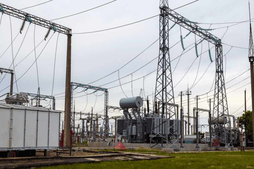
The Core Coil Assembly is the heart of a transformer, responsible for transferring electrical energy from one circuit to another through electromagnetic induction. It consists of two main parts:

Function of Core Coil Assembly
Components of Core Coil Assembly
- Core:
- Made of thin silicon steel laminations to reduce energy losses.
- Provides a low-resistance path for the magnetic field.
- Windings (Coils):
- Primary Winding: Receives electrical energy from the source.
- Secondary Winding: Delivers the transformed voltage to the load.
- Insulated with materials like paper, resin, or oil to prevent short circuits.
Process of Core Coil Assembly
Importance of Core Coil Assembly
Technical Specifications
Characteristics of CRGO electrical steel are affected by impurities, grain size, grain orientation and surface insulation. Even minor stresses, burrs, edge cambers or bends can increase core losses and magnetizing current significantly. Jay Bee Laminations Limited has the facilities to ensure proper handling and stress free processing of the material.
| General physical and mechanical properties of CRGO steel | |
|---|---|
| Density | 7.65 g/cm3 |
| Thickness of sheet | 0.23 – 0.35 mm |
| Silicon content | 3-4 % |
| Yield Point (relative to rolling direction) | 0 degrees • 330 N/mm2 90 degrees • 355 N/mm2 |
| Tensile strength | 0 degrees • 348 N/mm2 90 degrees • 412 N/mm2 |
| Elongation | 0 degrees • 11% 90 degrees • 31% |
| Number of bends | 0 degrees • 21 90 degrees • 15 |
| Hardness (Hv) | 204 |
| Stacking factor | 95-98% |
Grade classification of Electrical Steel
| Electrical Steel | Grade (BIS nomenclature) | Grade (Conventional nomenclature) | Thickness (mm) | Max Core loss (W/kg) 50 Hz | |
|---|---|---|---|---|---|
| @1.5T | @1.7T | ||||
| CRGO | 20HP70D | 20-70 | 0.20 | 0.52 | 0.70 |
| 23HP75D | 23-75 | 0.23 | 0.55 | 0.75 | |
| 23HP85D | 23ZDKH | 0.23 | 0.60 | 0.85 | |
| 23HP90 | 23M0-H | 0.23 | 0.64 | 0.90 | |
| 23HP100 | M3 (Low loss) | 0.23 | 0.68 | 1.00 | |
| 23CG110 | M3 | 0.23 | 0.70 | 1.10 | |
| 27HP90D | 27ZDKH | 0.27 | 0.66 | 0.90 | |
| 27HP100 | 27M0-H | 0.27 | 0.70 | 1.00 | |
| 27HP110 | M4 (Low loss) | 0.27 | 0.78 | 1.10 | |
| 27CG120 | M4 | 0.27 | 0.85 | 1.20 | |
| 30CG130 | M5 | 0.30 | 0.90 | 1.30 | |
| CRNGO | 35C230 | 0.35 | 2.30 | ||
| 50C470 | 0.50 | 4.70 | |||
| 50C600 | 0.50 | 6.00 | |||
Tolerance chart for dimensions of CRGO laminations (as per IS 3024)
| Attribute | Attribute Range/Value | Tolerance |
|---|---|---|
| Width | 0 – 100 mm 100 mm – 230 mm 230 mm – 400 mm 400 mm – 750 mm | +0.00 / -0.15 mm +0.00 / -0.20 mm +0.00 / -0.30 mm +0.00 / -0.50 mm |
| Length | 0 – 350 mm 350 mm – 1,000 mm 1,000 mm – 2,000 mm 2,000 mm – 3,000 mm 3,000 mm – 4,000 mm | +0.00 / -0.30 mm +0.00 / -0.60 mm +0.00 / -1.00 mm +0.00 / -1.50 mm +0.00 / -2.00 mm |
| Thickness | 0.23 – 0.27 mm 0.30 – 0.35 mm | +/- 0.025 mm +/- 0.030 mm |
| Mitering Angle | 45 degrees | +/- 5 minutes |
| Burr Height | 0.18 – 0.23 mm 0.23 – 0.30 mm 0.30 – 0.35 mm | 10 microns 15 microns 20 microns |
| Wave Factor | Material width > 150mm, Flatness deviation | Max. 1.5% of width |
| Edge Camber | Material width > 150mm | Max. 0.8 mm for length of 1.5m |
| Hole Dimension | Up to 34 mm | +/- 0.15 mm |

